


You have 0 items in your cart.

When using different types of probes, such as a voltage probe and a current probe, a small propagation delay difference exists between the probe pair. Small, but significant, this difference is caused by each probe's unique internal circuitry and cable length. This propagation delay difference is known as ‘skew' and creates an error when calculating switching loss or measuring timing. In the high speed switching of the switching power supply, the engineer is required to measure the timing of the control signal in nano seconds.
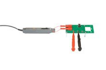
The 701936 Deskew correction signal source provides time synchronized current and voltage sources, which are necessary to calibrate and remove the skew characteristics from your oscilloscope-based power analysis measurements.
Yokogawa is the market leader in precision power measurement and is the only Test and Measurement manufacturer to offer both a (complete) range of power meters/power analyzers and digital oscilloscopes. We are uniquely able to offer unbiased advice in power measurement to our customers.
 The 701936 supports through-type CTs, such as those from AEM, LEM, and non-split core Hitec. This is achieved by using a removable wire loop which can supply 0.1 A.
Even though power measurement using an oscilloscope is less accurate than a power analyzer, it offers much higher bandwidth. It is particularly suitable for measuring high frequency switching losses in power supplies. It also provides a power measurement capability using a general purpose product, (which has other uses) which may be more acceptable to users who are not ready to invest in a true power analyzer or have limited budgets for test equipment.
The new 701936 Deskew Correction Signal Source improves accuracy in switching-loss measurements and similar measurements. These measurements are found in applications including switched-mode power supplies (SMPS), miniaturized power supplies and inverters, and applications where high-speed or fast-switching devices and waveforms are found.
Improvements over the previous 701935
The 701936 supports through-type CTs, such as those from AEM, LEM, and non-split core Hitec. This is achieved by using a removable wire loop which can supply 0.1 A.
The 701936 also supports more types of clamp-on current probes, such as the Yokogawa 701930 and 701931, for larger current measurements because a 1A source is added.
The 701936 uses a USB cable as a convenient source of power.
Unlike the previous 701935, the new source is not supplied in an enclosure in order that current clamps with larger jaws can be easily accommodated and the manufacturing costs minimized. The open style is similar to that of our scope competitors.
Main specifications
Output voltage: Approx. 0 to 5 V
Output current: Approx. 0 to 100 mA (small current)
Approx. 0 to 1 A (large current)
Fall time: Approx. 25 nsec (small current)
Approx. 250 nsec (large current)
Fixed time difference between
voltage and current : 2.3 nsec +/- 0.5 nsec (small current)
14.5 nsec +/- 1.0 nsec (large current)
Power supply: 5 Vdc / 100 mA (Avg.) via USB cable
Dimensions: 150 mm (W) x 48 mm (H) x 60 mm (D)
Weight: Approx. 100 g
| Name | Description | |
|---|---|---|
| Switched Mode Power Supply (SMPS) Analysis for Energy-Efficient Inverters, Rectifiers, Voltage Converters, and Phase Converters |
Whether your design involves an inverter, rectifier, DC to DC converter, or phase converter, switched mode power supply (SMPS )analysis and design efficiency is critical. This application handbook includes techniques for observing SMPS circuit internal waveforms, monitoring operating status, measuring efficiencies, and confirming the safety or loss in the devices used. |
Learn More |
| Area of Safe Operation Measurement for Switching Devices | Area of Safe Operation Measurement for Switching Devices | Learn More |
| Observation of Inverter Switching Waveforms | Observation of Inverter Switching Waveforms | Learn More |